Change Language :
Selection of the right twisterchain
twisterchain generally applicable

For machine elements, which travel both left and right in rotary motion, the angle of rotation results by the addition of both angles.
Legend
B = Outer limit
C = Machine
D = Fixed end
E = Upper limit
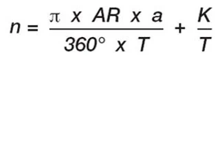
AR= Outer radius chain
IR = Inner radius of chain
R = Bending radius chain
X1 = installation space
X2 = AR-chain incl. clearance
T = Pitch
HF = Chain height incl. 50 mm installation space
H = Chain height
K = Surcharge for bending radius
hi = Inner height of the chain
ha = Outer height of the chain
α = Angle of rotation
Notes on the design of the twisterchain new by means of an example:
If you want us to do the project planning for you, then please use the igus® system planning. If you want to decide on the e-chain® and support trough yourself, please go through the following points and then enter the results in the calculation tool at the end of the section.
- Available installation space outer radius = 592 mm
- Available installation space inner radius = 311 mm
- α Angle of rotation = 220°
- Installation height = 466 mm
- Max. Ø of customer's cable = 22 mm (7.5xd)
Estimate the dimensions of the chain by means of the internal separation with filling and select the series, or verify the max. cable diameter and select the series using the next larger permissible Ø. (For the inner height, we suggest you take into account a cable clearance of approximately 20% of the chain inner height and width.)
Max. Ø cable diameter of twisterchain: TC32 = 25 mm | TC42 = 39 mm | TC56 = 53 mm Example: max. Ø cable diameter of customer 22 mm = Series TC32 (next larger)
Select the next smaller X2 of the chain from the available installation space of the outer radius. Please subtract from the measurement X2 80 mm, which results in the required outer radius AR. Selection of the chain outer radii, see measurement table X2 of the respective series.
Formula: AR = X2 - 80 mm
Example:
1. Available installation space outer radius 592 mm => 580 mm (X2)
2. X2 580 mm - 80 mm => AR 500 mm (the next smaller selected)
Add the addition of 25 mm to the available installation space of the inner radius and then select the next larger X1 of the chain. The maximum width Bi results from the selected value. Selection from the table of the corresponding series.
Formula: IRmin. = X1 + 25 mm
Example:
Available installation space of inner radius 311 mm + 25 mm = 336 mm => X1 350 mm = Bi 11 (108 mm)
Generally, the chain bending radius R is determined from the smallest bending radius of the cables. Selection from the table of the corresponding series.
Example:
1. Ø 22 mm (7.5xd) => 22 mm x 7.5 = 165 mm cable bending radius min.
2. 165 =>R 175 mm (next larger selected) is equal to => part no. TC32.11.175/500
An allowance of 170 mm is added to twice the value of the selected chain's bending radius R.
Example:
R 175 mm x 2 + 170 mm = H 520 mm

Hint: Always round up the resulting number of links! The mounting brackets can be mounted only on the outer links of the twisterchain new. So the number of links must always be raised to the next higher odd number! twisterchain new is generally applicable: For machine elements, which travel both left and right in rotary motion, the angle of rotation results by the addition of both angles.
Suggestions for the layout of the twisterchain new without additional components
| Series | AR [mm] | FZmax. [kg/m] α0°- 180° | FZmax. [kg/m] α180°- 360° | v to AR permitted [m/s] | a to AR max. [m/s2] |
|---|---|---|---|---|---|
| TC32 | 400 | 4 | 2 | 1 | 2 |
| 500 | 4 | 2 | 1 | 2 | |
| 600 | 4 | 2 | 1 | 2 | |
| TC42 | 400 | 6 | 3,6 | 1 | 2 |
| 500 | 6 | 3,6 | 1 | 2 | |
| 600 | 6 | 3,6 | 1 | 2 | |
| 650 | 5 | 2,7 | 1 | 1,5 | |
| 750 | 4 | 1,8 | 1 | 1 | |
| 850 | 4 | 1,8 | 1 | 1 | |
| TC56 | 650 | 8 | 5 | 1 | 2 |
| 750 | 8 | 5 | 1 | 2 | |
| 850 | 8 | 5 | 1 | 2 |

